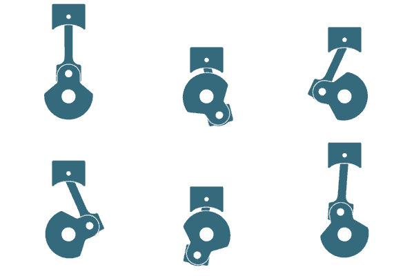
These types of solutions are becoming a mainstay in digital marketing and training with talented students and teams pushing the boundaries further every day.
Meet Adam Guernsey, Visual Media Project Coordinator

There are multiple ways to incorporate Visual Media into training and to utilize CAD beyond the initial product design and development. These types of solutions are becoming a mainstay in digital marketing and training with talented students and teams pushing the boundaries further every day. The possibilities are nearly limitless and the only restrictions are how far the imagination can go. Knowing what hurdles you may face and how to best optimize CAD for your end product will ultimately help move your creative project forward with the best results.
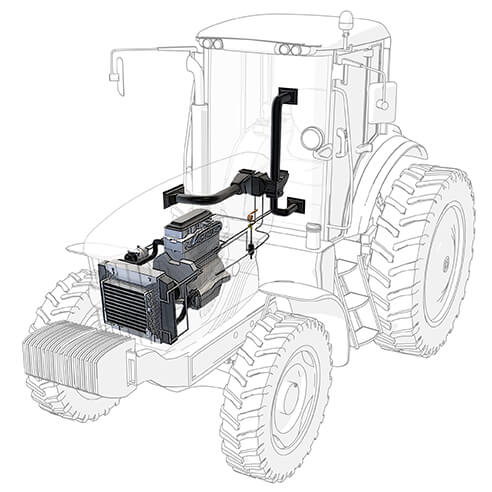
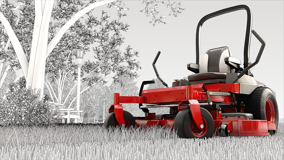
Line art has been used in technical publications for many years. Getting photographs of the internals of a Sugar Cane Harvester could take many, many hours. Why not use something that has already been created? CAD data can easily create complex line art images in far less time. If you need to show an internal section at a specific line weight, your best bet is to use CAD based graphics.
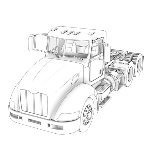
Do you have a new product being developed right now? Do you want to start selling or promoting the product before production? You guessed it, you want to use the CAD to make striking visualizations of you product. If your product is too expensive or heavy to affordably ship, using realistic CAD images is a great cost reduction tool.
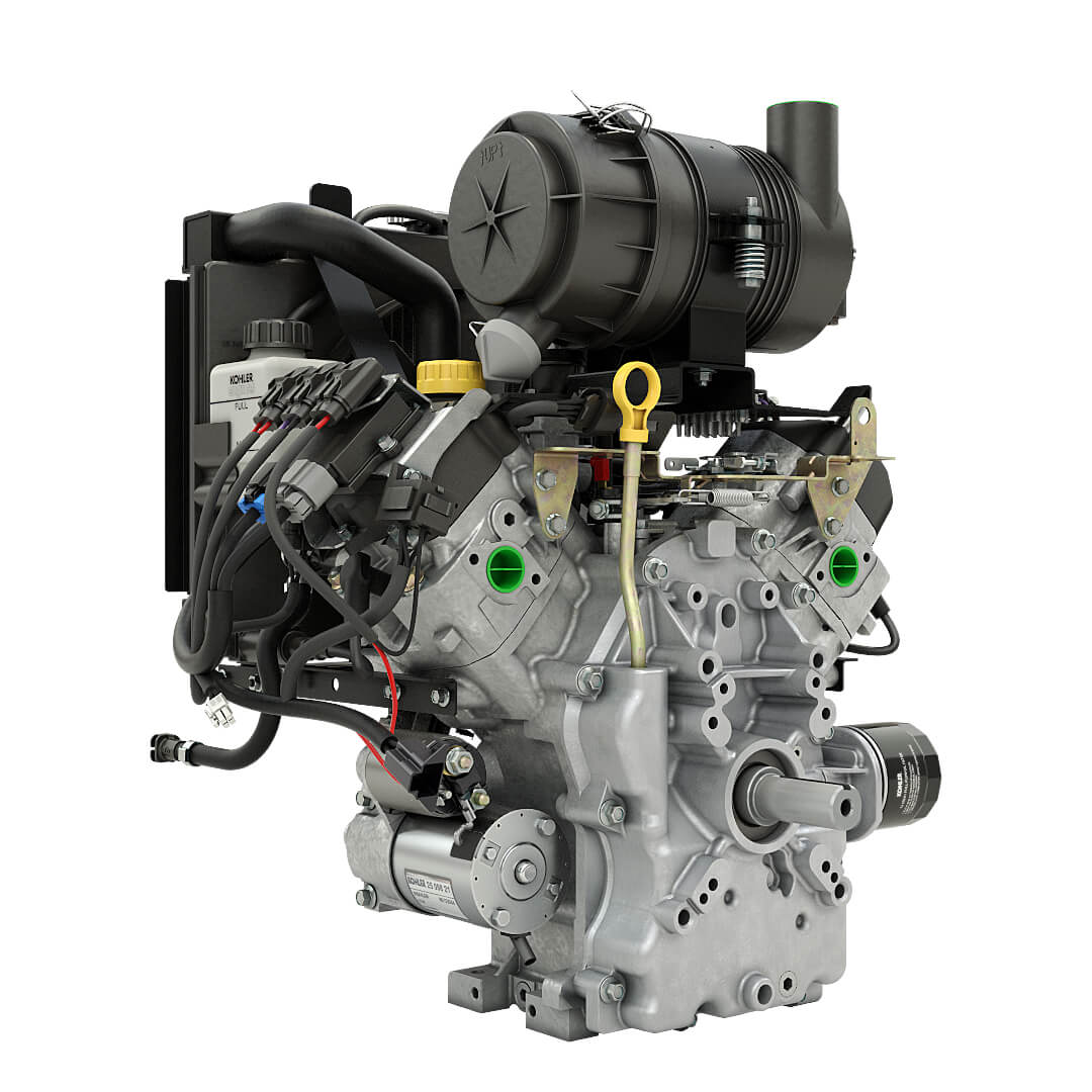
Component identification is extremely useful for training. You want your staff and clients to know exactly what they are looking for before they begin work. Using CAD based art, you can get a good look at all sides of the machine and components. With a little knowledge of programming you can even make it interactive and contain descriptions of each component.
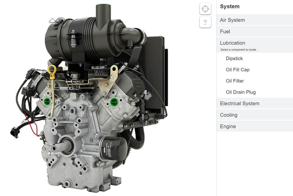
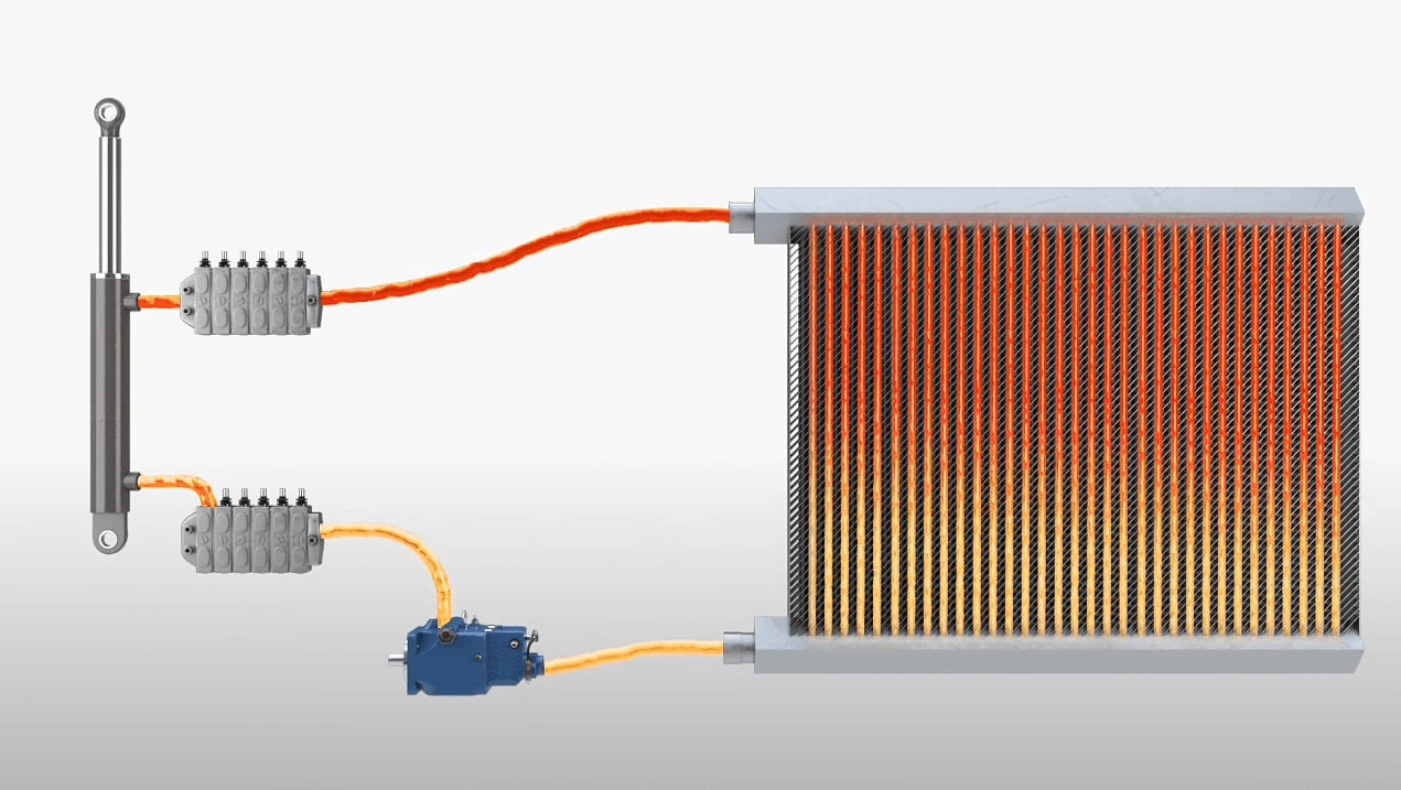
Sometimes understanding how systems such as hydraulics and electricity work can be difficult enough, but getting good representations of those systems for training can also be difficult. Using the CAD from specific machines we can identify the components that make up those systems and simulate how the system works using a 3D environment. Being able to trace the flow from component to component in their respective locations on the machine can be an invaluable tool for training.
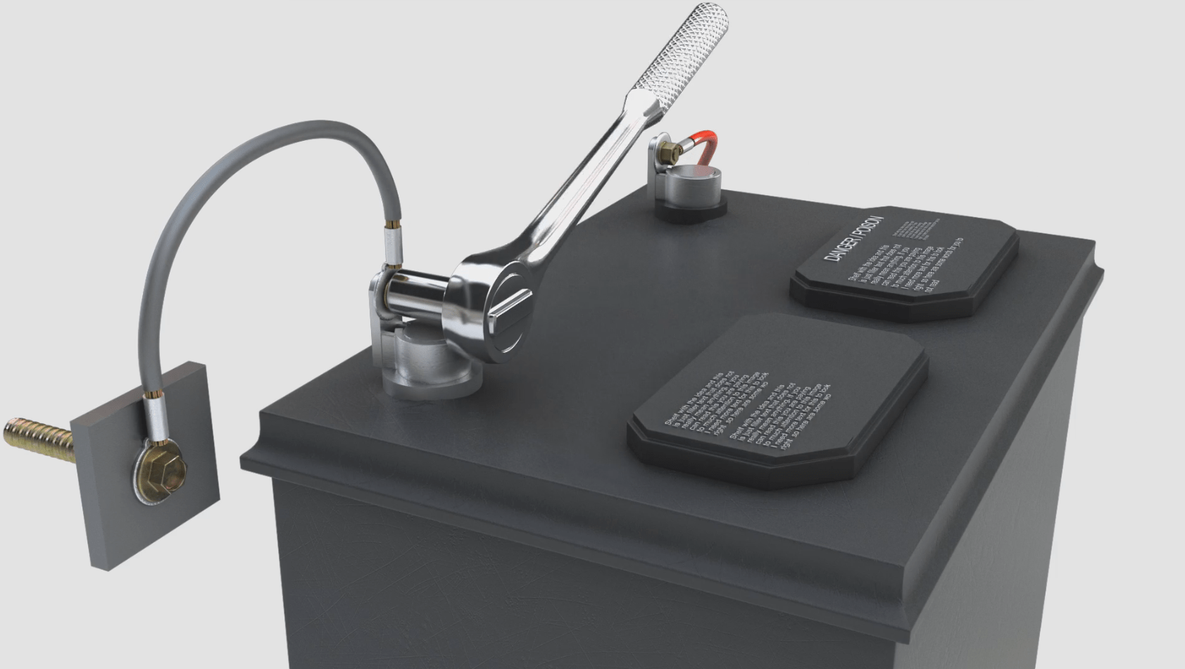
Animations that show procedures can be huge time-savers. Imagine the time it takes to walk to the tool chest and get the correct tools for every step of a procedure. If this was a video, the videographer would need to be onsite while all of that “nonessential” video time is taking place. With animation, the magic all happens within virtual space and can be produced faster.
Marketing animations are sharp, exciting and can get people pumped about a new or existing product. Animation is wide-spread in the world of marketing and can be used a variety of ways. One of the most beneficial uses of animation in Marketing is the bling factor. With all of the different types of software and visual effects that can be produced, making a product stand out visually in new and unique ways is a perfect fit for animation in Marketing.
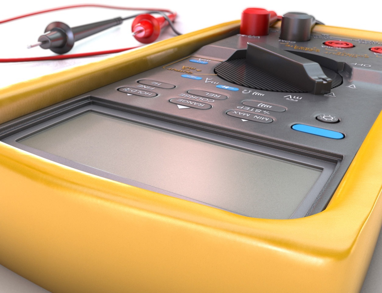
Once CAD files are transitioned into a workable format, the types of art that can be created is nearly limitless, bringing more value to the lifecycle of the CAD data.
There are more than a dozen CAD file types and software on the market today. Some of the big names are Solid Works, AutoCAD, Pro E/Creo, Catia, and Parasolid. Here at Almon, we have converted nearly all of these files types and many more. We determined that STEP files are the most efficient format for creating 3D art with our clients CAD.
STEP files are our choice because they are capable of storing precise data, BOM lists, and color information. When using CAD in a 3D art pipeline having parts distinguished with unique colors is extremely helpful.
Getting a BOM list with the proper configuration of a machine from a client is essential. Imagine that you have a tractor that can be equipped with 12 sets of tires or treads but the image that you need to make has a very specific tire tread. If you didn’t have the correct BOM configuration, you may spend a lot of time between yourself and your client verifying which set of tires or tracks is correct.
We use the Autodesk Suite of Software for 3D files and Adobe Software Suite for rendered assets in post-production. Both of these suites are industry standards in the world of Visual Media.
When we convert our client’s CAD files we alter the format of the file, it changes the original 3D file’s surface information. Imagine that you have a perfectly shaped sphere in CAD. When we convert the CAD, that perfectly shaped sphere gets small changes in the surface, similar to a diamonds facets. This doesn’t change the appearance of the object much but creates a safe, non-reconstructive file to work with. Most CAD files are very large in size so this also streamlines the file into something more manageable for our 3D software.
The process of optimizing our client’s CAD files creates a “neutral format” that strips away precise dimensions, manufacturing processes, machine tolerances, and all proprietary information.
When the finished art is created from the CAD files the machine or equipment will still look great and appear exactly as it should, but this optimization process ensures that it would be impossible for anyone to remanufacture or 3D print the machine in its original state.
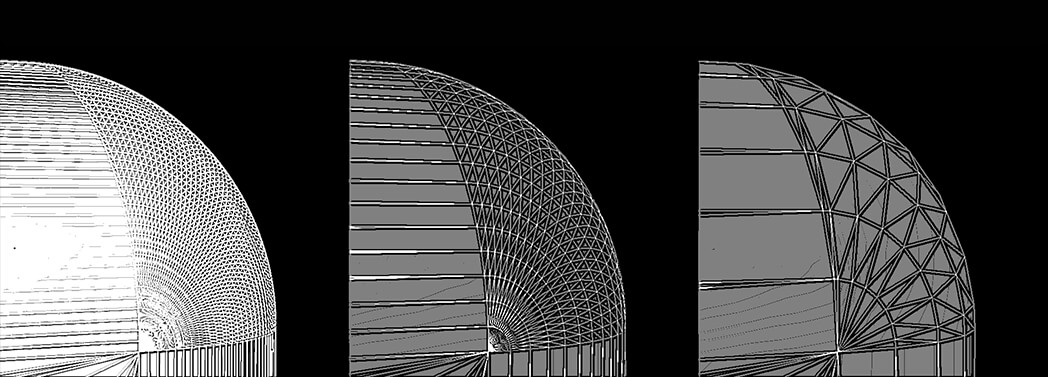
Let’s talk about ways that CAD can be “no good” or not as efficient as “good” CAD.
In a CAD file, duplicates of CAD objects can be overlapping each other or stacked directly on top of one another. This generally occurs when multiple engineers work on the same product line with different feature variations over an extended period of time but are required to keep everything in one file. Overlapping object and duplicates can be easily overcome with a complete BOM list by simply “turning off” layers and items that you don’t need.
A problem that has a much more complicated and time-consuming solution is Shrinkwrapping. This generally occurs during the export of a CAD file. Most times it is simply a missed check box during export. No matter how it happens though, it can take an extensive time toll on a project. You can tell that a file is shrinkwrapped when multiple components that should be separate are fused together. These files are time consuming because most components in a product are made up of different materials such as metals or plastics. When an object is shrinkwrapped it becomes increasingly difficult to get these various materials on the multiple objects.
When CAD is shrinkwrapped or has excessive duplicates, block modeling machines may be a better solution. Block modeling is the creation of objects in 3D software by a modeler. This process does takes time, but can render excellent results. Measurements and photos can be taken from the physical products to create 3D art that, when rendered, looks visually accurate to the physical product.
Realtime applications such as driving simulators and AR/VR applications are becoming increasingly popular in training. These applications allow for Virtual “Hands on” training when it’s too expensive or impossible to train on the real thing.
AR/VR applications need 3D assets that have a low polygonal count or in other words are “game ready”. Game Ready assets are created out of polygons and designed for optimal performance.
CAD files have an incredibly high polygon count, making it virtually impossible to run inside a realtime environment. In order to successfully get CAD files into a software engine the files must be optimized using a low-poly workflow. These software engines are typically referred to as game engines.
Without reducing polygon count the “Game Engine” would crash. Here is some of the things to keep in mind when reducing polygon count.
In CAD data a single bolt could have up to 500 polygons. Most of these polygons do not hold value i.e. they do not contribute to the overall shape or silhouette of the model. Therefore, they can be removed to ease the burden of the “game engine” from storing them in memory. The fastest way to do this would be called Retopologizing or Retopo.
Retopo is drawing a low poly model on top of a high poly model while retaining the overall shape/silhouette. Any polygon that does not contribute to the shape should be removed.
This process should be done by a 3D artist, and cannot be successfully automated yet. There are software solutions being developed to automatically convert CAD models into game engine ready assets but none have successfully displayed the craftsmanship necessary for true polygon optimization. A fully optimized game asset takes not only the polygons into consideration but many other factors such as texture resolution and efficient UV layout.
There are solutions currently where you can take CAD data into CAD designed 3D engines but these solutions are expensive and time consuming. The 3D engines are not industry standard realtime game engines. Students are learning how to use 3D Game Engines such as Unity and Unreal in colleges today and these are the tools our industry should pay attention to.
These software tools will become more and more utilized in training and technical publications as the years go on. It’s not hard to predict that every technical publications company or manufacturer will have teams fluent in these game engines and have training material created by them, if they don’t already. If your company is researching training in simulators/VR/AR they are, most likely, using the Unity or Unreal game engine.
